Check List for approval of ESP (Engineering Scale Plans)
Check list for approval of ESP (Engineering Scale Plans) issued by Engineering department…
Engineering Scale Plan is the basis for yard layout of a station and Signalling plan. Utmost care has to taken by the divisions while preparing and scrutinizing the ESP’s.
It has been observed that the Engineering Scale Plans are not being checked thoroughly by the divisions comparing with the last approved ESP, SlP and with site conditions in case of discrepancy between approved ESP and SIP before forwarding the plans for the approval of Headquarters. This is leading to consumption of lot of time at Headquarters tor getting attended the observations noted during the scrutinization of ESP. lf the religious scrutiny is done at divisional level lot of time can be saved both at divisional and headquarters level.
For the guidance and follow up, the list of items to be checked during the approval of ESP are described below…
| Sr. No | Items to be checked | Reference |
| 1 | 1 TITLES AND NUMBERING OF DRAWINGS | IRWM Para 904(a) |
| (Title block size – 170mmX65mm with basic information) | ||
| i Name of Railway | ||
| ii Name of Division / Construction Organization | ||
| iii Name of work | ||
| iv Drawing Number | ||
| v Alterations, if any, with full particulars in red on existing plan | ||
| 2 | Spelling of station names, with kilometer and chainage centre line of station building with chainage as 000:00 | IRWM Para 906(a) (iii) |
| 3 | Designations and serial numbers of all lines and sidings with direction of traffic (Up & Dn line) should be shown. | Engg Code Para 468 & SEM-I Para 8.6.2. (iii) & (Viii) |
| 4 | The names of the nearest junctions or terminal stations on either side with length of block section including branch line / mid section sidings, if any, should be shown. | SEM-I Para 8.1.2 & IRWM Para 906(a) (ii) |
| 5 | Track centre between the lines and siding for running line should not be less than 6.3 mtr. | IRWM Para 906(a) (xiv) & ACS 13 to IRSOD 2004 |
| 6 | Requirement of Dead ends / over run for isolation and simultaneous reception. All standard dead ends should carry the wording “Not fit for stabling” and length should not be less than 120 mtrs for MACLS. | SEM-I Para 8.6.2. (iv) |
| 7 | Infringements of standard dimensions, if any, should be shown in tabular form. | IRWM Para 906(a) (xvi) |
| 8 | CSR from FM to FM of all lines and sidings with chainages should be shown. | IRWM Para 906(a) (xiv) |
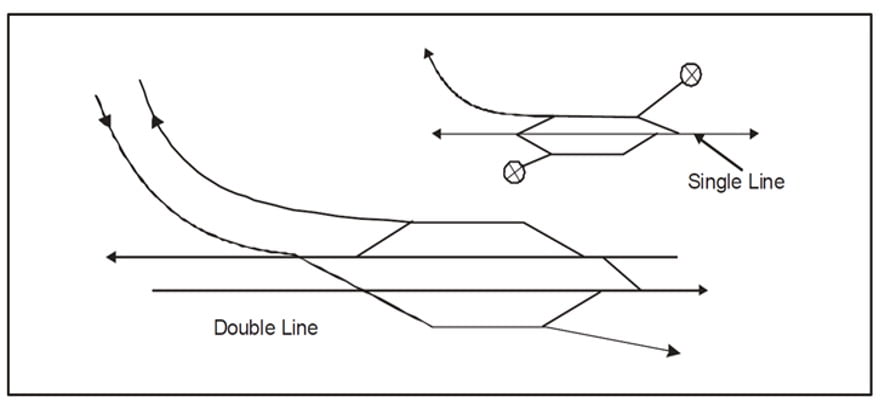
| 9 | Fouling mark should be placed at the first glued joint towards berthing portion of the line from SRJ of the concerned point as shown below. | GR 4.56, SEM-I Para 7.85.2(b) & SEM-II 17.11 |
| 10 | Type of Platform (i.e. Passenger or goods) with length and width and their heights above rail level should be shown. | IRWM Para 906(a) (xiv) |
| 11 | Gradient posts with chainages up to 2.5 kms in rear of outer most points on either side. | SEM-I Para 8.6.2. (iv) |
| 12 | There must be no change of grades within 30 meters of any points or crossings. | SOD 2004, Chapter II Para-2 d |
| 13 | Railway land boundary with the distance from main line should be shown. | IRWM Para 906(a) (v) |
| 14 | Complete description of bridges with chainages should be shown. | IRWM Para 906(C) |
| 15 | LC Gate No. and class and its kilometreage/chainages, latest ATVU whether manned or unmanned up to 2.5 Kms in rear of outer most points on either side should be shown. Road width of LC Gate should also be maintained if gate is interlocked. If Road width is more than 08 mtrs, then road divider and double barrier should be shown | IRWM Para 906(a) XV, SEM-I Para 8.6.2.(vi) |
| 16 | LC Gate to be clear of all running lines, Loop lines, dead ends and sidings. Gate lodge should be shown. | CRS letter MB/195 dt 29.06.04 |
| 17 | Description of work ( to assess scope of S&T work ,Signalling requirement changes in standard of interlocking, PI or MACLS etc.) and scale of plan in meters should be mentioned. | SEM-I Para 8.6.2. (i) |
| 18 | North directions should be shown. | SEM-I Para 8.1.5, IRWM Para 906(a) (i) |
| 19 | Chainages of points, traps, fouling mark (FM), gradient posts should be mentioned. In case of alteration in the yard chainages of old points, FM, LC Gate to be checked with respect to either previous Engg. Plan or Sig. Plan in force | IRWM Para 906(a) (xiv) |
| 20 | Means of Isolation (Snag dead end / trap point etc.) should be provided to achieve the mandatory isolation. | SEM-I Para 7.72.1 |
| 21 | Trap points with isolation as required , opening away from the important running lines. | Rly opening for publlic carriage passenger rule 2005 Para-36, 8(c)(ii) |
| 22 | Length of overlaps / dead end to be of 120 mtrs for MACLS and 180mtrs for LQ for signal overlap. | GR 3.40(3) |
| 23 | Type of turnout i.e. whether 1 in 8/2, 1 in 12 or 1 in 16 crossover for passenger lines, goods lines, siding etc. should be mentioned. 1 in 8.5 with curved switches only permitted. | SEM-I Para 8.6.2. (xiii), GR 4.11 |
| 24 | Preferably the gradient should not be continuously steeper than 1 in 260 between distant & home in single distant territory & between inner distant & home signal in double distant territory; otherwise Block overlap would be increased from 180.00 mtr to 300.00 mtr. | Rly Board Letter 2010/Safety ( A&R)/19/23 dated 02.11.12 |
Download the complete checklist in PDF format for approval of ESP…


0 Comments