Check List for Signalling Plan approval
For execution of S&T projects in Indian Railways, Signal Interlocking Plan (SIP) is most important document. SIP’s are prepared based on the Engineering Scale Plan (ESP). There are some important points to be kept in mind while approving or preparing the SIP. So, Here is the summarised check list for Signalling plan approval.
Check List for Signalling plan approval
Download Checklist issued by Western Railway- Click Here
-
Title Block
- Format, font and information in Title Block is as per standard.
- Name of station: Shown Correctly in English & Hindi.
- Name of work with brief description is mentioned.
- Plan No. is correct as per register maintained by Open Line.
- Supersedes Signalling Plan, ESP Plan numbers are correct.
- Other information in title block columns is correct as per Working Time Table (WTT).
-
General Layout
- Station Building symbol (PI/RRI/EI) is shown with center line & KM.
- Yard layout is correct, number of lines, points, sidings, traps etc.. as per ESP
- Work to be dismantled is shown dotted as per ESP & referred SIP.
- Description of UP, DN, main, loop lines/sidings is correct and shown wherever needed.
- Name of adjacent junction, block and ‘D’ class stations with distance line is given distance between lines.
- Signals are placed wherever required as per yard layout and symbol aspect is correct.
- Gradient of station yard is more than 1:400
- All chainages are matching for Paints, Dead Ends, LC gate, FM, P/Fend, sidings, traps, bridges etc with that of ESP.
-
GRADIENT POSTS
- Chainages and grades of all Gradient Posts are correct, no Gradient Posts is missing.
- Consecutive gradients are matching.
-
SIGNALS
- Aspect, Chainages, numbering is correct.
- Signalled movements / routes are shown on lines.
- Aspect control chart is correct & matching with that of signal aspect.
- If gradient is less than 1:300 in approach of Home signal, GWB at 600m from Distant.
- If gradient is less than 1:260 in approach of Home, then Home signal to be provided at 300m from FP/BSLB if cris-cross movement is to be done.
- BSLB is placed for trailing point/ station with no loop (DL station).
- Starters placing Glued joint 3m beyond FM, starter 0-3m from glued joint.
- SH7/SH44: 13m from SRJ of point
- Advance Starter: 120m from SH7/SH44.
- Signal line: Home at 300m from Adv. Starter.
- Double Line: Home at 180m from FP/BSLB.
- In case of LC (OSL) gate in vicinity, follow CSTE DRG No.6197.
- Distant Signal at 1000m beyond Home Signal.
- Goods Warning Board at 400m/600m beyond distant signal as the case may be.
- SH7/SH44 are to be provided, other shunts as per requirement e.g. for a siding shunt for going in & going out is needed.
- Stop Boards where signals are not given.
-
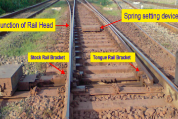
POINTS
- Numbering is correct
- Chainages & description (1:12 or 1:8.5) is shown correctly.
- Crack handle groups are grouped & numbered properly.
-
TRACKS
- Numbering is correct
- Maximum length DC track circuit 350 m for practical purposes.
- One Point, One track circuit
- Calling ON track – 5RL, Adv. Starter track -3RL
- When another Point originates from a line before FM if previous point is placed, track may be fouling – marked as (F)
- Berthing generally has odd no. of track circuits.
- Point and LC gate tracks should be as small as possible.
- Minimum track circuit length is 26m.
-
LC Gates
- Name, Class, Manned/Unmanned, InterLocked/Non-InterLocked ATVU, Chainage, Centre Line to be shown with gate.
- If Manned – gate lodge is shown & gate equipments are shown near it.
- Sliding boom : at WSL LC gate- Sliding boom to be provided. At OSL LC Gates- Sliding Boom to be provided if interlocked.
- Interlocking of LC Gates required for all WSL LC Gates, and OSL LC gates should only be interlocked if is in vicinity of station & ATVU>20000
- Lifting barriers – Mechanical or Electrical?
- Direction of barrier locking is right as per traffic direction.
- If road width is >8m, two lifting barriers are provided.
- If new barrier is provided, earlier is cut, and new one is made in red.
- WSL: gate control slot, gate console, emergency triple lock is shown. Corresponding control at station provision to throw to danger in case of emergency for all signals directing towards LC gate.
- OSL: gate console & gate panel both.
- Gate telephones- Individual for each LC, corresponding telephone at station.
- For OSL gates in vicinity, distance from first point is given, accordingly signals as per CSTE DRG No.6199
- Road signals & description shown. Normal aspect should be checked as per WTT.
-
Block Instruments
- Which type of block instrument – symbol & discription. Axle Counter resetting & co-operation arrangement.
- HADAC symbol for block sections
- For MSDAC DPs in the yard should be shown.
- Track naming – AXT.
Other Items to be checked-
- Control Panel – Spare for Signal, CH, point, slot are shown.
- Bridges- Name& description is correct.
- Crank Handle box is shown.
- Previous Plan History
- Note for containing of signals, SLB, starter within 3m of GJ, dispensation.
Once this SIP Check List is followed thoroughly during approval of SIP, chances of mistakes in SIP would be very less. So, this check list for approval of Signalling Plan must be followed thoroughly.
Read more about…
- Pre-commissioning checklist for Electronic Interlocking (EI)
- Electronics Interlocking EI TAN and Specifications
- SMS generation on failure of EI
- List of IRSSE Officers and Batches


1 Comment
Anonymous · January 28, 2025 at 1:58 am
It’s very useful information in railways