Notice: Function WP_Scripts::localize was called incorrectly. The $l10n parameter must be an array. To pass arbitrary data to scripts, use the wp_add_inline_script() function instead. Please see Debugging in WordPress for more information. (This message was added in version 5.7.0.) in /home4/railmu7v/public_html/wp-includes/functions.php on line 6170
Notice: Function WP_Scripts::localize was called incorrectly. The $l10n parameter must be an array. To pass arbitrary data to scripts, use the wp_add_inline_script() function instead. Please see Debugging in WordPress for more information. (This message was added in version 5.7.0.) in /home4/railmu7v/public_html/wp-includes/functions.php on line 6170
Notice: Function WP_Scripts::localize was called incorrectly. The $l10n parameter must be an array. To pass arbitrary data to scripts, use the wp_add_inline_script() function instead. Please see Debugging in WordPress for more information. (This message was added in version 5.7.0.) in /home4/railmu7v/public_html/wp-includes/functions.php on line 6170
Notice: Function WP_Scripts::localize was called incorrectly. The $l10n parameter must be an array. To pass arbitrary data to scripts, use the wp_add_inline_script() function instead. Please see Debugging in WordPress for more information. (This message was added in version 5.7.0.) in /home4/railmu7v/public_html/wp-includes/functions.php on line 6170
Skip to content
The Indian Railway Service of Signal Engineers (IRSSE) is a prestigious Group A Gazetted cadre of the Government of India. The cadre is managing the Signal & Telecom department and its operations of the Indian Railways.
A proud moment for S&T fraternity. A long awaited mission is successfully completed today. Congratulations to Mr Kashinathji for becoming first Member (S&T). Great day for entire S&T fraternity.
Salute to all IRSSE officers who have been valiantly pursuing this. Hope from now, we can contribute more to the safety and development of Railways and there by nation development with technological advancement, improved maintenance practices and dedicated S&T team, in the years to come.
(i) The post of Director General (Signal & Telecom.) should be re-designated as Member (Signal & Telecom); and
(ii) Shri N. Kashinath, IRSSE, presently working as Director General (Signal & Telecom), should continue against the re-designated post of Member (S&T).
Shri N. Kashinath is an IRSSE 1980 batch officer. On retirement of Shri Akhil Agrawal, he took over the charge of post of DG(S&T).
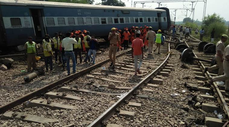
New Farakka Express derailed near Rae Bareli in Uttar Pradesh around 6 am on 10.10.2018
In the derailment at least seven people died and around 35 injured after nine coaches and the engine of the New Farakka Express (Train No. 14003) derailed near Rae Bareli in Uttar Pradesh at around 6 am on 10.10.2018. Several passengers on the train were trapped. more…
Immediate Recommendations of CRS
The Commissioner of Railway Safety , Shri S. K . Pathak conducted the enquiry and Immediate Recommendations are issued
“In accordance with Rule 3 of Statutory Investing into Railway accidents Rules issued by Ministry of Civil Aviation, after the preliminary investigation of the above subject accident and based on the facts revealed in the inquiry by the witness, followings immediate recommendations are made to Railway Administration in the interest of safety in train operation:-
Railways should decide on a reasonable time as well as reasonable number of attempts after which a point not responding to command given from control panel is to be declared as failed. Necessary changes in data logger software should be done to log such point failure in data logger exceptional report. Action as per G&SR should be ensured after point is declared as failed.
Provision of Magnetic Lock in Relay room door to keep electronic log of number of times the door is opened must be ensured in working condition at all stations having data logger. Failure of this magnetic lock shall reflect in DRM’s daily position.
All the location boxes provided at each end of yard in point zone should be replaced by the location hut which should house signalling gears pertaining to various points on one end of the yard. The location huts must also be kept under double lock with one key being in the possession of SM and it should be opened by S&T staff only after following same procedure as prescribed for the relay room opening. Recommendations No. 2 and 3 will ensure that there is no tempering in signalling circuit either in relay room or in location boxes.
Drivers should be trained to ensure that use of SA-9 brake (Independent loco brake) in case of emergency should not be restored to unless completely unavoidable. More particularly, SA-9 must not be used on turn outs and curves as this may exerts excessive unbalanced forces & torque due to momentum of the trailing load.
Data logger terminal with report printing and simulation facility should also be available with Chief Controller Coaching in the control room so that immediate access of data is available with chief controller also.
Training of Data logger architecture, usage, interpretation and report generation should be given to operating control officials.”
Conclusion of CRS report…
More or less these recommendations are already in place and Data logger is being used extensively for these purposes…
Point flashing, and point failure is being monitored through Data logger today also.
Relay Room Door lock is also being monitored through Data logger and it is part of daily position of Sr.DSTEs.
The Location huts at point zone is good recommendation but its practicality restrict the implementation of this recommendation. It wont be possible to maintain the signalling gears without the key of huts. it is always not possible to construct location hut due to site constraints. maintenance of location huts is also subjective of various other factors.
Why not operation of trains should be S&T department???
Recommendation no. 5 & 6 are basically indicates the operation of trains should be with S&T department, who has the access to data at all the times even in emergency. And also S&T department has the trained employees, who understand the data. Basically the Chief controller of operation must have access to data and knowledge of data interpretation, which can be very well done by S&T department.
The Railway Minister (MR) had reviewed the Health Care System of Indian Railway on 29.08.2018 and had decided to install the CCTV and WiFi system to monitor the CLEANLINESS and other activities of the Hospital.
The installation of WiFi system will help in exchange of patient records and in tele-medicine for better medical care of the patient.
The Tele medicine can be provided by the expert doctors from the remote place over the Internet to railway hospitals, where the experts are not available.
The Railway board (DG/S&T) has set the target date of December 31, 2018 to complete the installation of WiFi and CCTV cameras in all the Divisional and Zonal Railway Hospitals.
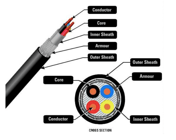
The laying of Signalling cables require laying of various types of Cables in the station yard as per the Signalling plan. Cables which are mainly used inside the building are called Indoor cables and cable which are laid in the outdoor are called Outdoor Signalling Cables.
To drive the Point, Signal and Track Circuits cables are laid from the Relay Room to actual gear/equipment installed in the field (outdoor). Thus, the cable laying require details planning as per the yard layout and signalling scheme of the station before laying of the cables.
This is most important activity for starting of cable laying for any station. This requires thorough understanding of signalling plan and interlocking scheme of the station, like…
No. of Point Machines, Signals, Track Circuits, and other equipments.
Type of Track Circuiting ex. DC tracks, MSDAC, AFTC etc.
Make of Equipments ex. different type of axle counter require different cables.
A cable core distribution plan is required to be prepared for each installation. Detailed instructions are elaborated in below sections.
Track Crossing Plan
During laying, cables has to cross the track, thus for crossing the track either open trench is made under the track or boring is to be done under the track. As per instructions issued and for cable laying can be done as per JPO issued from the Railway Board.
Thus, the track crossing plan has to be prepared so that the P-Way Inspector can allow the track crossings of cables.
Now a days, open trench under the track is not permitted, so the track crossing by Boring Method is the only option.
The Location detail is prepared as per the Cable Termination in the location boxes. It shows the information that how the functions are feed from the location box and how the cables are connected with other cables.
CTR Details
Cable Termination Rack (CTR) details are prepared for the termination of cables on the Cable Termination Rack.
Basically, CTR are used to connect the Outdoor (cables) with the Indoor (cables). On the CTR, Outdoor cable is connected on the one side of terminal, and the Indoor cable is connected on the other side of the terminal.
Cable Testing Records
The records of cable laying during the laying should be properly maintained in a cable laying register.
Details to be noted in columns-
Type of Cable (6C, 12C, 24C, 6Q etc…)
Manufacturer of Cable
Cable Drum Number
Length of Cable in Drum
Length of Cable used/laid in the trench
Top meter (reading from the cable)
Bottom Meter (reading from the cable)
From (Location box)
To (Location box)
Meggering Report
This is also an important document, which keeps the details of cable testings. With the megger, cable must be checked for its insulation with respect to other conductors and earth as well.
So, the meggering report must be prepared “Before the Cable laying” and “After the cable laying” for all the cables.
It should be jointly tested with the openline staff and record should be maintained.
Approval of Plans
The Cable Route plan, Track Crossing Plan must be got approved from the divisional officers as well like… Sr.DSTE, Sr.DEN and Sr.DEE. If the work is being executed by the construction department then the approval from Construction officers like Dy.CE/Construction, Dy.CEE/Construction is also required in addition to divisional officers.
The Cable Core Chart, Location Details and CTR details must be approved by the executing officials i.e. SSE, JS/SS and JAG officers.
The Cable Meggering Report must be jointly signed by the openline SSE and construction SSE, if the work is being executed by the construction organisation.
In AC electrified areas cables shall be laid underground only.
Cables may be laid underground, either in the trench, in ducts, in cement troughs, in pipes or in any other approved manner.
Cable is generally laid parallel to the track beyond Home signal with minimum deviations and on one side of the yard.
As far as possible, cable shall be crossed only at two locations, i.e. one crossing on each side of the yard.
The cable laid parallel to the track shall be buried at a depth of minimum 1.0 metre (top most cable) from ground level. Those laid across the track must be minimum 1.0 metre below the rail flanges.
However, in case of rocky soil, the depth may be reduced suitably.
For laying of tail cables the depth shall not be less than 0.50 metres.
In theft prone areas the cables may be laid at a depth of 1.2 metres with anchoring at every 10 metres.
The minimum width of manually made cable trenches shall be kept as 0.3 meters.
The cable shall be covered with a layer of sand or sifted earth of 0.10 metre thickness and thereafter a protective cover of trough or a layer of bricks shall be placed.
Normally, not more than 12 cable are to be laid in one trench.
It is recommended that cables are laid in RCC duct up to home signal on both side of the station and may be extended up to distant, if required. This will also help later for laying of additional cable later without carrying out trenching.
Before starting cabling work location boxes shall first be erected so that cable after laying is directly taken inside location box.
(a) Cable laying near the Track
(i) Outside the station limits, the cables shall generally be laid at not less than 5.5 metre from the centre of the nearest track.
(ii) Within the station limits, the trenches shall preferably be dug at a distance of not less than 3 metre from the centre of the track, width of the trench being outside the 3 metre distance.
(iii)At each end of the main cable an extra loop length of 6 to 8 metre shall be kept burried at same depth as that of cable in the same trench to ensure that cable is free from theft/outside interference.
(b) Laying of different type of cables in same trench
Cables should be laid in the following order, starting from the main track side: i) Telecommunication cable ii) Signalling cable iii) Power cable Minimum separation between telecommunication cable and signalling cables -10 cm.
The signalling cables must be separated from power cables by a row of bricks between them.
Note: As per practice in some railways, before laying of cables, stripes, dots or any other symbol may be marked throughout the outer sheath of cable with different colour for different cables. This will help in easy and quick identification of ends when cables are cut due to theft or excavation work or any other reason, thereby reducing the restoration time.
(c) Cable laying in ducts
RCC, masonry or any other approved type of ducts may be used for laying the cable. The ducts shall have suitable covers and shall rest on walls of duct.
(d) Laying cable in solid & rocky soil
In the rocky ground the cable shall be laid normally on layer of sifted earth of 0.05 metres thickness previously deposited at the bottom of the trench. Cable shall be covered with the layer of sand or sifted earth of 0.1 metre thickness.
Alternatively, concrete/GI/CI/PVC/DWC-HDPE pipe shall be used if number of cables is small.
If number of cables is large, RCC duct shall be used.
A row of bricks shall be placed lengthwise on the top and jointed with cement mortar and a layer of concrete with cement plaster.
(e) Laying in special soil condition
If it is unavoidable to run cables through abnormally high acidic or alkaline soil or through sewages, cables may be laid in the concrete/GI/CI/PVC/DWC-HDPE pipes
(f) Cable laying in residential area
The cable shall be specially protected on both sides up to a distance of about 300 metres beyond the building line, protected by means of concreting of 50 mm.
(g) Cable laying in large yard and suburban area
Main signalling cable shall be laid in RCC ducts/DWC-HDPE pipes.
Tail cables shall be laid through DWC-HDPE pipes of suitable sizes and buried in trenches at a depth of not less than 1000 mm from ground level.
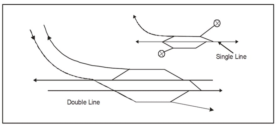
(h) Track crossing
How track crossings should be done.
As far as possible, cable shall be crossed only at two locations, i.e. one crossing on each side of the yard.
When a cable has to cross the track, is shall be ensured that.
The cable crosses the track at right angles;
The cable does not cross the track under points and crossings and
The cable is laid in concrete/GI/CI/PVC/DWC-HDPE pipes or suitable ducts or in any other approved manner while crossing the track.
Cable laid across the track must be 1.0 metre (minimum) below the rail flanges.
No digging shall be done below the sleepers. Digging work while crossing a track shall be done between sleepers in the presence of a Railways representative.
(i) Road Crossing
The cable is laid in concrete/GI/CI/PVC/DWC-HDPE pipes, suitable ducts or in any other approved manner while crossing the road at the depth of 1 metre from the ground level. It shall extend 1 metre (minimum) on each side of the road keeping in view the future increase of width of the road.
Suitable precautions may be observed while laying of pipes and refilling the trench depending upon the type of road (e.g. heavy or light traffic, broad or thin) so as not to block the road traffic for a longer period.
Whenever a cable is laid across an important road, particularly one with a special surface, a spare pipe may be laid, through which a cable can be drawn when required. It will be advantageous to leave a lead wire of G.I. wire in the pipe for drawing the cable in future.
(j) Cable laying on bridges/culverts
Wherever practical, the cable may be taken underground across the drain bed at a suitable depth for crossing small culverts with low flood level.
Where cable may not be taken underground across the drain bed, cable shall be taken on the culvert through GI/DWC-HDPE pipe of suitable sizes.
When cables have to cross a metallic bridge, they shall be placed inside a metallic trough which may be filled, as an anti-theft measure, with sealing compound. The cable shall be supported across the bridge in a manner which would involve minimum vibrations to the cable and which will facilitate maintenance work.
In case of arch bridges, cable shall be taken through GI/DWC-HDPE pipes on top of the arch adjoining the parapet wall. The pipe shall be covered with ballast.
(k) Laying near to sleeper
In places where cables are to be laid within 1 metre from sleeper end, digging beyond 0.50 metre shall be done in the presence of an official from Engineering Department, and the laying of the cable and refilling of trench shall be done with least delay. Laying may be undertaken under block protection as needed.
(l) Jumper cables for track circuits
Jumper cable should be tied with the nearest sleeper, on wooden sleepers using iron clamps/hook and on PSC sleepers using clamps.
Cable shall be buried underground in the line of sleeper and taken to TLJB, where sleeper ends.
Wherever required, cable may be laid in DWC-HDPE pipe.
Jumper cable shall be laid at least 0.5 metre below ground level excluding ballast depth.
Jumper cable shall be laid neatly in squared manner and shall not be kept in loose coils above the ground near TLJB.
Top surface of TLJB shall not be 1 feet above rail level.
(m) Cable laying in monsoon season
It is not advisable to lay cables in monsoon. When however cable laying is necessary during the monsoon season, the cable ends shall be inserted in a pipe sealed at one end and the pipe buried. Termination work shall be started only when there is likelihood of a clear weather for three or four days.
(n) Entry of cable at cabin, relay room, location boxes etc.
All cable entry points in cabin, relay room, battery room, SM’s room, location boxes, location huts, junction boxes, etc. must be closed with suitable masonry works, sand covered and plastering/RCC slab to prevent entry of rats etc.
Cable shall be protected on both sides up to a distance of 10 metre beyond building line of cabin, relay room, battery room, SM’s room and 1 metre beyond location boxes, location huts, junction boxes etc.
The cable must not press against the edge of the solid support where the bed changes from solid support such as a foundation/masonry to soft support such as soft soil. The soft soil near the edge must be tamped and the cable raised slightly.
(o) Cable termination
All the core of the cable (used or spare) shall be terminated on approved type terminals in cabin/SM’s office or apparatus cases. Each core so terminated will be provided with identification ferrules with letters or/numbers embossed on them as per requirement of circuitry.
Termination of signalling cable on CT rack in relay room and in location boxes shall be done duly using identification marking on cable and on conductors/terminals. A proper marking and termination practice ensures quick and easy restoration during failures.
(p) Testing of cable
Before the cable is laid in the trench, a visual inspection of cable shall be made to see that there is no damage to the cable. It shall be tested for insulation and continuity of the cores. Thereafter, the cable shall be laid into the trench. Record of insulation and loop resistant must be maintained.
(q) Supervision of cable laying
The work shall be supervised at site personally by an official of the Signal & Telecommunication Department not below the rank of a JE/SE/SSE (Signal).
Orders will be given by the Inspector in charge only. He will be assisted by others at vulnerable places to inform him of the position and possible danger.
All concerned staff shall have full knowledge of their duties and the material handled by them.
No work shall be started unless all types of materials, tools consumable materials and staff are available. Location boxes and junction boxes shall be in position. If the cable ends are left in the ground unattended, damage is likely to take place.
Following record shall be maintained by JE/SE/SSE in-charge of the work/section:-
Cable route plan
Cable distribution chart
(iii)Cable termination diagram
Cable Testing Record : Summary Sheet, including supply details etc.
(r) Special requirements in 25 kV AC electrified area
Only unscreened cable shall be used.
Screened signalling cable may be used on signalling installations where screened cable is already in use and site condition demand its further use.
PVC insulated PVC sheathed and armoured unscreened cable to an approved specification (IRS-63) shall be used for carrying signalling circuits. Only approved type (IS-1554) power cable shall be used for signalling purposes.
The screened cable, if used, shall be PVC insulated, armored and to an approved specification IRS S-35.
The cable shall be so laid that it is not less than one meter from the nearest edge of the mast supporting the catenary or any other live conductor, provided the depth of the cable does not exceed 0.5 meters. When the cable is laid at a depth greater than 0.5 meters, a minimum distance of 3 meters between the cable and the nearest edge of the O.H.E structure shall be maintained. If it is difficult to maintain these distances, the cable shall be laid in concrete/heavy duty HDPE/Ducts or any other approved means for a distance of 3 meters on either side of the Mast. When so laid, the distance between the cable and the mast may be reduced to 0.5 meters. These precautions are necessary to avoid damage to the cable in the event of the failure of an overhead insulator.
In the vicinity of traction sub stations and feeding posts, the cable shall be at least one metre away from any metallic part of the O.H.E and other equipment at the substation, which is fixed on the ground, and at least one metre away from the substation earthing. In addition, the cable shall be laid in concrete or heavy-duty HDPE pipes/or other approved means for a length of 300 meters on either side of the feeding point. As far as possible, the cable shall be laid on the side of the track opposite to the feeding post.
In the vicinity of the switching stations, the cable shall be laid at least one metre away from any metallic body of the station, which is fixed in the ground, and at least 5 meters away from the station earthing. The distance of 5 meters can be reduced to one metre provided the cables are laid in concrete pipes/ heavy-duty HDPE pipes/ducts or any other approved means.
Where an independent Earth is provided for an OHE structure, i.e. where the mast is connected to a separate Earth instead of being connected to the rail, the cables shall be laid at least one metre away from the Earth.
Where there are O.H.E structures along the cable route, the cable trenches shall as far as possible, be dug not less than 5.5 meters away from the centre of the Track.
In a cable run, the number of circuits carrying 300V at any given instant shall not exceed three.
Directly recruited UPSC batch of The Indian Railway Service of Signal Engineers (IRSSE 2016 (P))
Ministry of Railway has offered appointment letter to join IRSSE 2016 Group ‘A’ service for the 30 officers recruited based on result of Engineering Service Examination (ESE) 2016. Training of IRSSE officer is mainly given by IRISET.
For installation and commissioning of Electronic Interlocking at any station of Indian Railways, EI TAN issued by RDSO should be followed strictly. Compliance of Technical Advisory Note (EI TAN) is must for any EI installation.
Latest Technical advisory note No: STS/E/TAN/3012, Ver 2.0 dated 10.08.2016, which supersedes the earlier Technical Advisory Note No. STS/E/TAN/3012 Ver. 1.0 dated 28.08.2014,
For execution of S&T projects in Indian Railways, Signal Interlocking Plan (SIP) is most important document. SIP’s are prepared based on the Engineering Scale Plan (ESP). There are some important points to be kept in mind while approving or preparing the SIP. So, Here is the summarised check list for Signalling plan approval.
In case of LC (OSL) gate in vicinity, follow CSTE DRG No.6197.
Distant Signal at 1000m beyond Home Signal.
Goods Warning Board at 400m/600m beyond distant signal as the case may be.
SH7/SH44 are to be provided, other shunts as per requirement e.g. for a siding shunt for going in & going out is needed.
Stop Boards where signals are not given.
POINTS
Numbering is correct
Chainages & description (1:12 or 1:8.5) is shown correctly.
Crack handle groups are grouped & numbered properly.
TRACKS
Numbering is correct
Maximum length DC track circuit 350 m for practical purposes.
One Point, One track circuit
Calling ON track – 5RL, Adv. Starter track -3RL
When another Point originates from a line before FM if previous point is placed, track may be fouling – marked as (F)
Berthing generally has odd no. of track circuits.
Point and LC gate tracks should be as small as possible.
Minimum track circuit length is 26m.
LC Gates
Name, Class, Manned/Unmanned, InterLocked/Non-InterLocked ATVU, Chainage, Centre Line to be shown with gate.
If Manned – gate lodge is shown & gate equipments are shown near it.
Sliding boom : at WSL LC gate- Sliding boom to be provided. At OSL LC Gates- Sliding Boom to be provided if interlocked.
Interlocking of LC Gates required for all WSL LC Gates, and OSL LC gates should only be interlocked if is in vicinity of station & ATVU>20000
Lifting barriers – Mechanical or Electrical?
Direction of barrier locking is right as per traffic direction.
If road width is >8m, two lifting barriers are provided.
If new barrier is provided, earlier is cut, and new one is made in red.
WSL: gate control slot, gate console, emergency triple lock is shown. Corresponding control at station provision to throw to danger in case of emergency for all signals directing towards LC gate.
OSL: gate console & gate panel both.
Gate telephones- Individual for each LC, corresponding telephone at station.
For OSL gates in vicinity, distance from first point is given, accordingly signals as per CSTE DRG No.6199
Road signals & description shown. Normal aspect should be checked as per WTT.
Block Instruments
Which type of block instrument – symbol & discription. Axle Counter resetting & co-operation arrangement.
HADAC symbol for block sections
For MSDAC DPs in the yard should be shown.
Track naming – AXT.
Other Items to be checked-
Control Panel – Spare for Signal, CH, point, slot are shown.
Bridges- Name& description is correct.
Crank Handle box is shown.
Previous Plan History
Note for containing of signals, SLB, starter within 3m of GJ, dispensation.
Once this SIP Check List is followed thoroughly during approval of SIP, chances of mistakes in SIP would be very less. So, this check list for approval of Signalling Plan must be followed thoroughly.
Check list for approval of ESP (Engineering Scale Plans) issued by Engineering department…
Engineering Scale Plan is the basis for yard layout of a station and Signalling plan. Utmost care has to taken by the divisions while preparing and scrutinizing the ESP’s.
It has been observed that the Engineering Scale Plans are not being checked thoroughly by the divisions comparing with the last approved ESP, SlP and with site conditions in case of discrepancy between approved ESP and SIP before forwarding the plans for the approval of Headquarters. This is leading to consumption of lot of time at Headquarters tor getting attended the observations noted during the scrutinization of ESP. lf the religious scrutiny is done at divisional level lot of time can be saved both at divisional and headquarters level.
For the guidance and follow up, the list of items to be checked during the approval of ESP are described below…
The names of the nearest junctions or terminal stations on either side with length of block section including branch line / mid section sidings, if any, should be shown.
Requirement of Dead ends / over run for isolation and simultaneous reception. All standard dead ends should carry the wording “Not fit for stabling” and length should not be less than 120 mtrs for MACLS.
LC Gate No. and class and its kilometreage/chainages, latest ATVU whether manned or unmanned up to 2.5 Kms in rear of outer most points on either side should be shown. Road width of LC Gate should also be maintained if gate is interlocked. If Road width is more than 08 mtrs, then road divider and double barrier should be shown
Description of work ( to assess scope of S&T work ,Signalling requirement changes in standard of interlocking, PI or MACLS etc.) and scale of plan in meters should be mentioned.
Chainages of points, traps, fouling mark (FM), gradient posts should be mentioned. In case of alteration in the yard chainages of old points, FM, LC Gate to be checked with respect to either previous Engg. Plan or Sig. Plan in force
Type of turnout i.e. whether 1 in 8/2, 1 in 12 or 1 in 16 crossover for passenger lines, goods lines, siding etc. should be mentioned. 1 in 8.5 with curved switches only permitted.
Preferably the gradient should not be continuously steeper than 1 in 260 between distant & home in single distant territory & between inner distant & home signal in double distant territory; otherwise Block overlap would be increased from 180.00 mtr to 300.00 mtr.